LPDA MIMO & Non-MIMO Antenna Information AU - VK3HJQ
 This thread has been locked for further replies. You can start a new thread to share your ideas or ask questions.
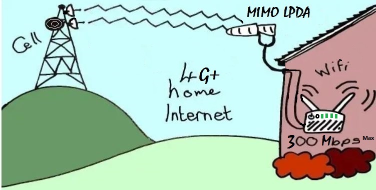
LPDA MIMO & Non-MIMO
Antenna Information AU
John vk3hjq
Actual Portable speed test
MR600 V2 12v solar powered
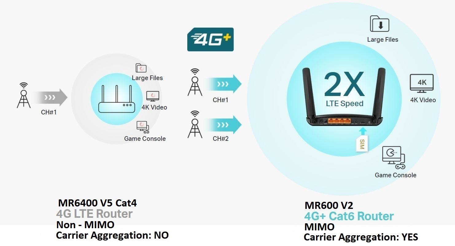
Maximum speed achieved with 2 x LPDA Antennas was 140Mbps/40Mbps (MIMO) @ 8km from the cell tower, compared to 1 magnetic mount 7dBi antenna on the roof @ 40Mbps/20Mbps (Non - MIMO).

Solar panel 30V @ 8.3A / Battery 13.7V @ 16.8A


********************************************************************************************************************************
Tech Info


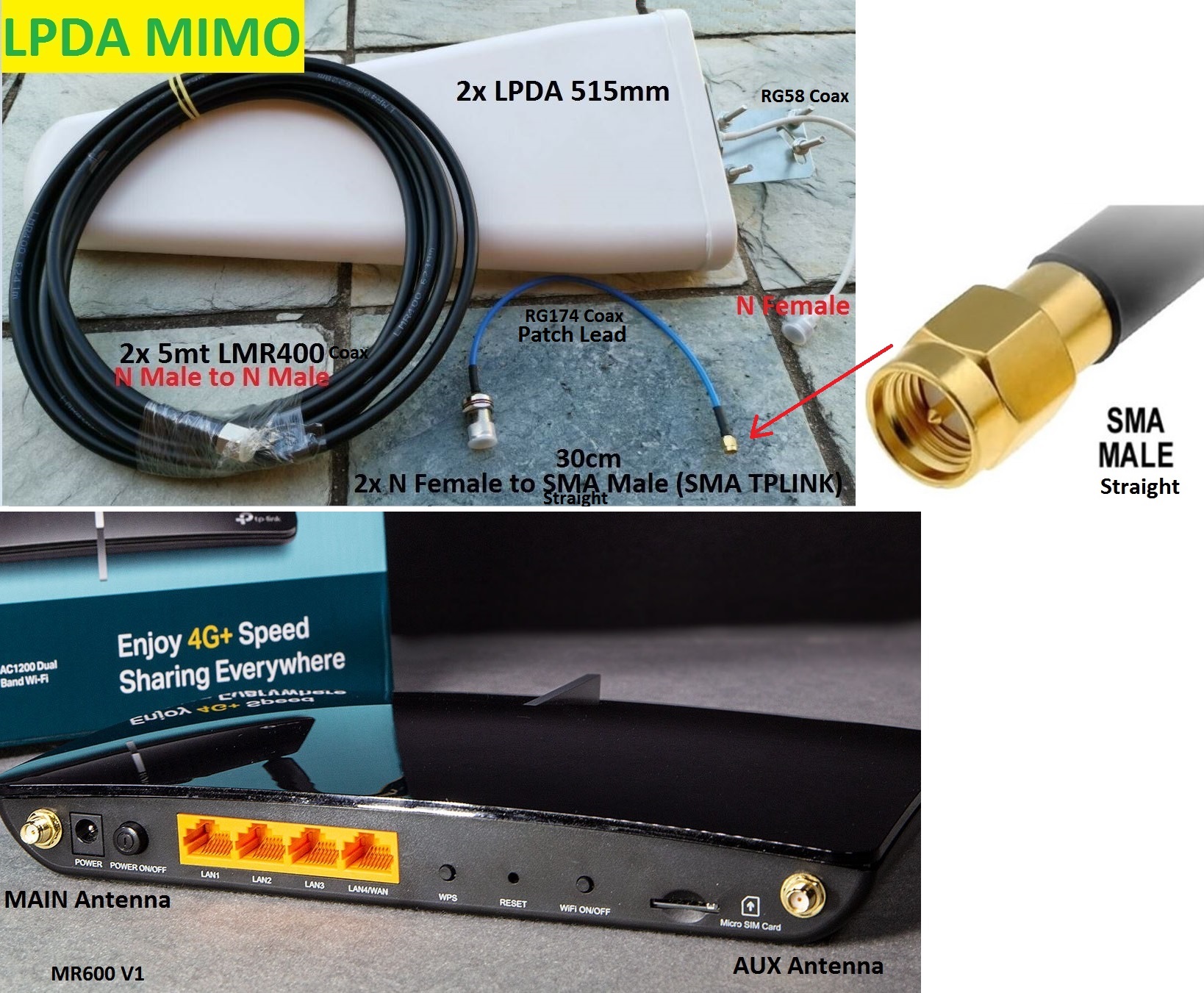
NOTE: The LPDA Antenna is feed from the front, meaning the coax is connected to the front of the Antenna & not the back.


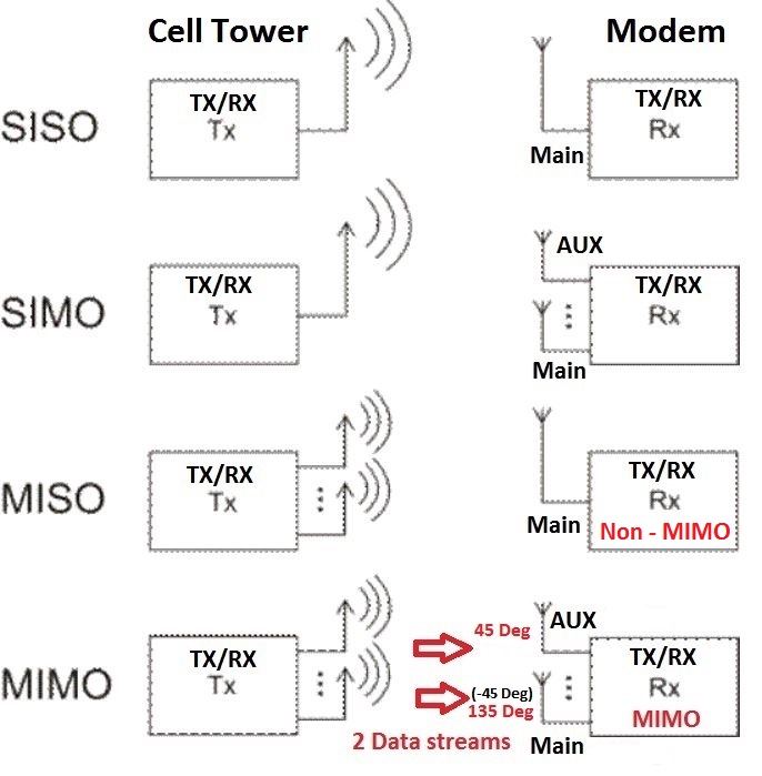
Non - MIMO Connection
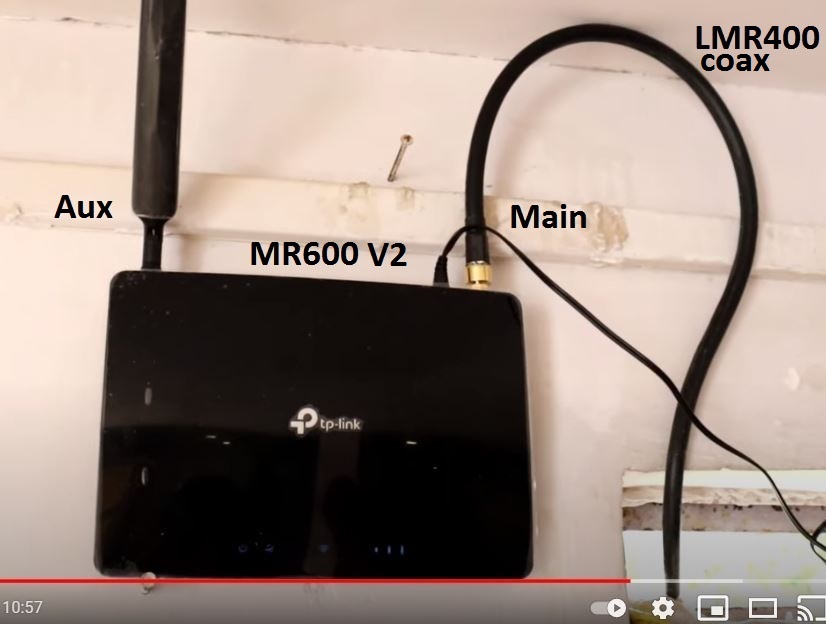
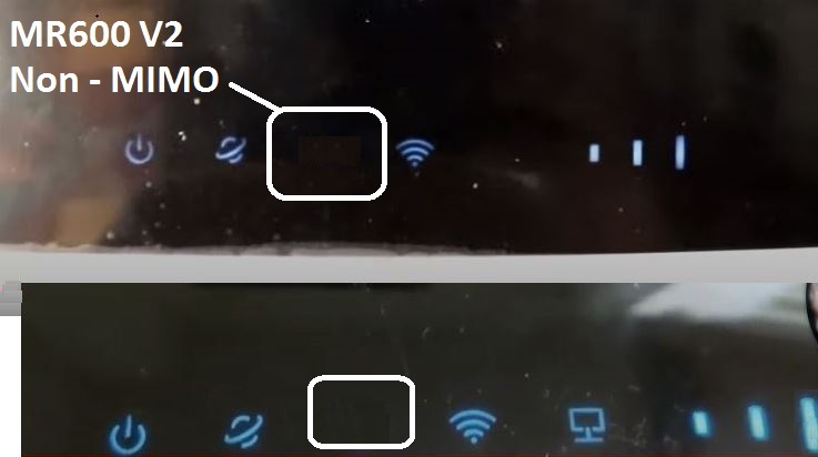
Always have 2 Antennas connected, it will NOT work with ONLY the AUX Antenna connected, (unless a very high signal is present) but it will work with the Main Antenna connected.
NOTE: (Never leave the Antenna input open circuit with no 50ohm load connected, meaning always have both Antennas connected even if ONLY using 1 external LPDA Antenna)


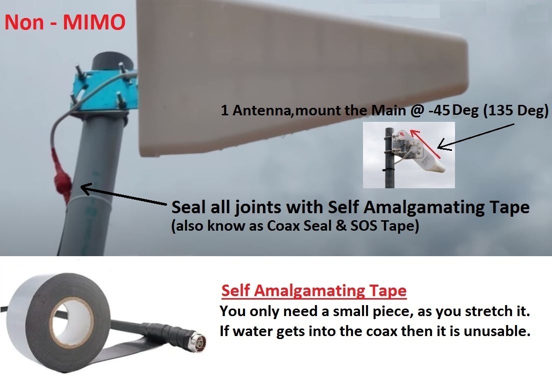
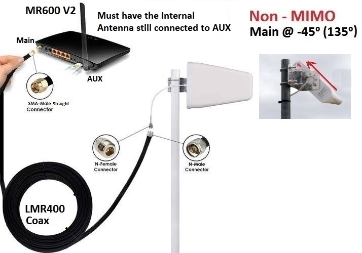
1 Antenna (LPDA) Main (-45 Deg/135 Deg) connected to the Main Antenna Input for Non - MIMO operation. (MUST have internal Antenna still connected to AUX)
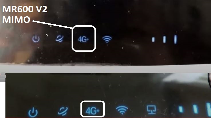
MIMO Connection

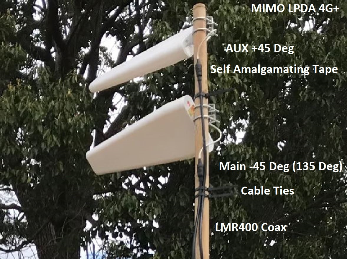
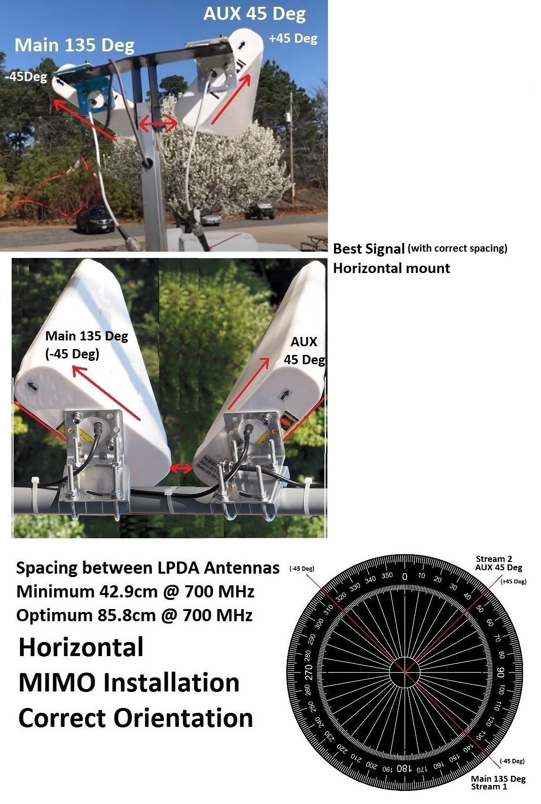
2 Antennas (LPDA) Main & AUX, AUX @ 45 Deg & Main @ 135 Deg (-45 Deg) then connect to the (Main & AUX) Antenna inputs respectively.


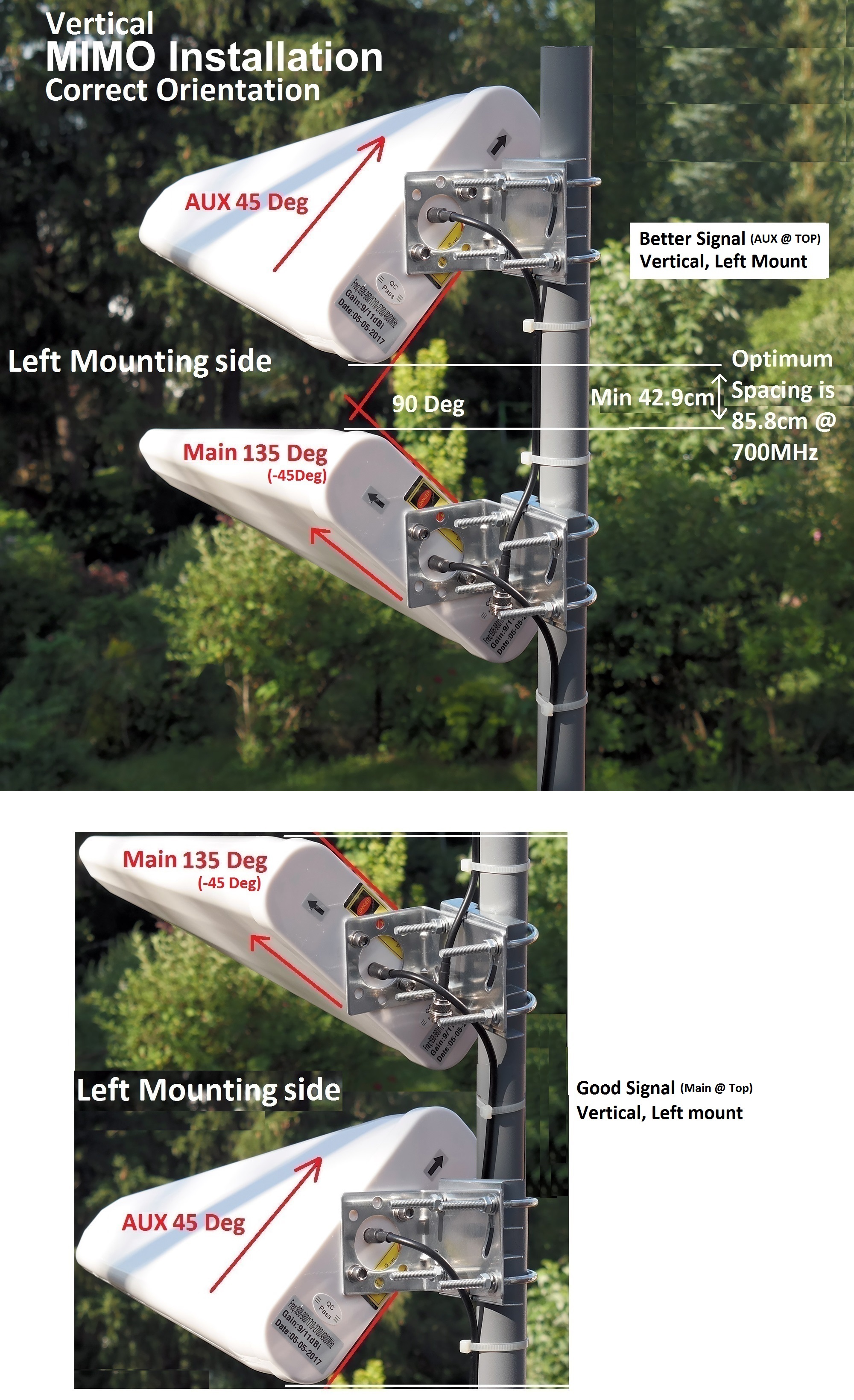
You can mount the LPDA MIMO Antennas vertically on either the Right or Left (Left preferred) side of the mast/pole, always make sure the arrow/s on the LPDA Antenna/s is pointing up.  & the Antennas should be mounted a minimum of 42.9cm (1 wavelength @ 700MHz) apart & for Optimum performance, mount them 85.8cm (2 wavelengths @ 700MHz) apart.
You can also mount them the other way around if you require a better Main signal, (because of the Antenna spacing required) but this could drop your MIMO signal out too & go back to Non MIMO operation, this means now having the Main @ the Top & AUX @ the Bottom/Underneath, Main @ 135 Deg (-45 Deg) & AUX @ 45 Deg.
For the BEST performance, a better solution would be to mount them horizontally instead to allow for the Optimum spacing required @ 700MHz (lowest frequency used) of 85.8cm apart. (both LPDA Antennas MUST still be pointing up  @ the correct angle)
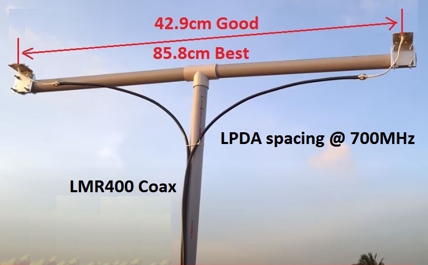


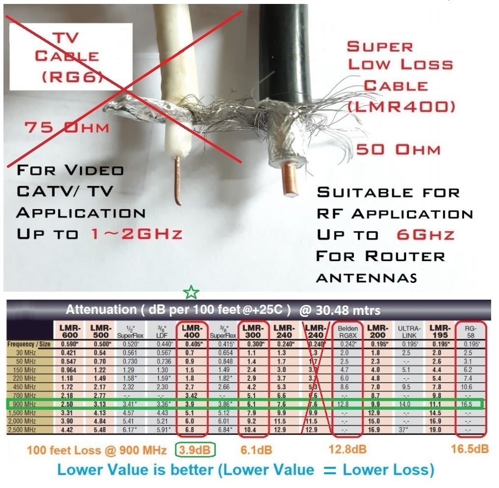

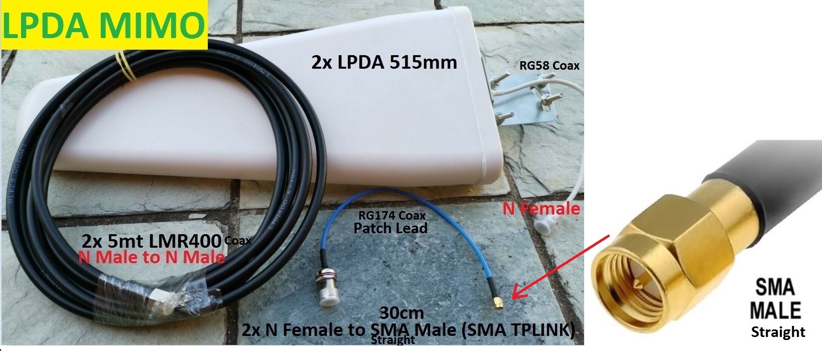
Less loss if you DONT need to use Patch Leads to the Modem/Router, sometimes it is necessary to do this for cable conversion & to stop your Modem/Router being pulled off the Bench/Table & it also makes it a lot easier to connect the heavy coax (LMR400) into your Modem/Router as well.


Adaptor can add >1 -1.5dB of loss, Remember 3dB is 1/2 your signal lost.

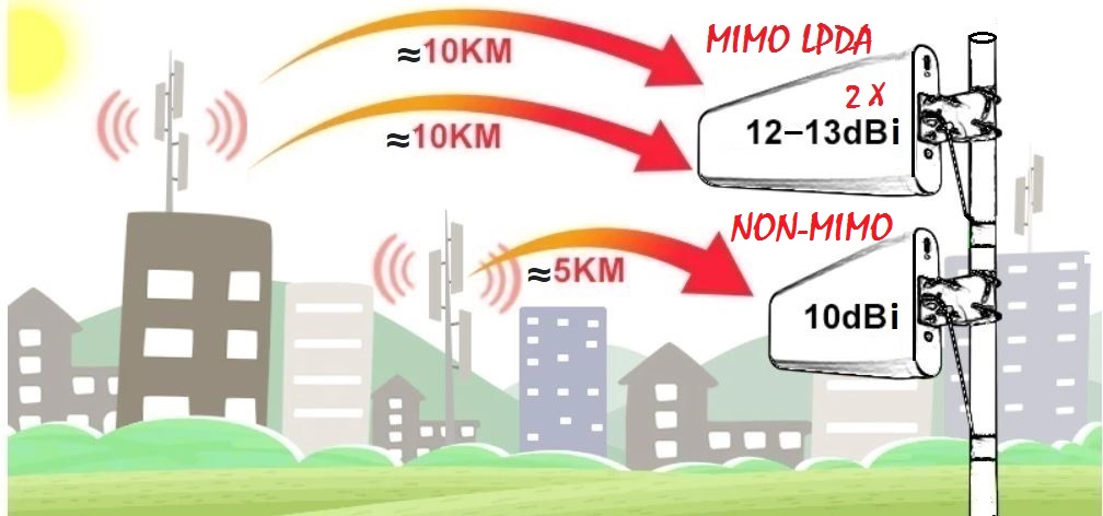
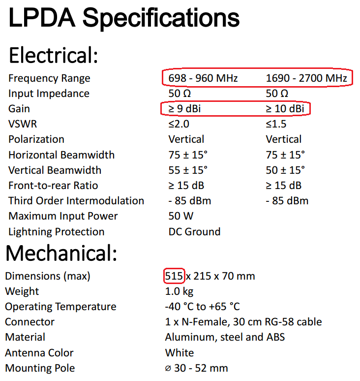
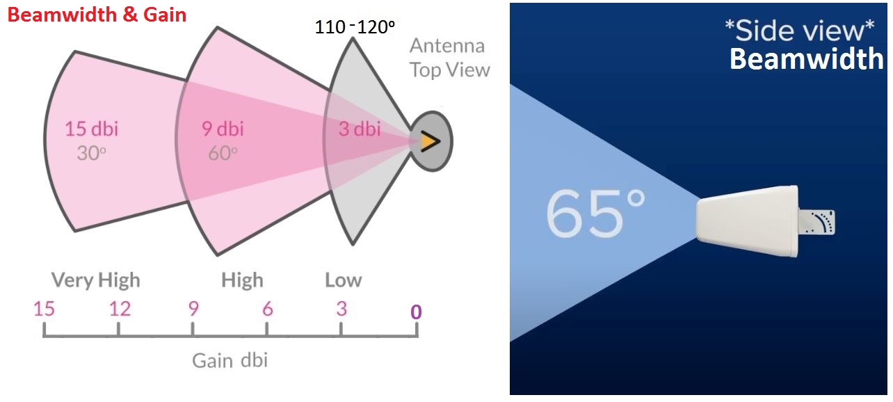
12dBi (9.85dBd / 9.85dB) & usually less gain @ the lower frequencies, down by a further >2dBi

What's inside these LPDA Antennas.


Other types of LPDA Antennas, remember 2 are required for MIMO


8 -12dBi (694 - 3800MHz) @ 5G (3600MHz) 3dBi


Always check the frequency range on Dish (Parabolic) Antenna feed horns (1700 - 3800MHz, 2 x 30dBi & 1700 - 2700MHz, 2 x 24dBi) Remember 4G/+ 700 - 2700MHz & 5G 3800MHz AU
E&EO - All the above Information, pictures & linked content etc. has been sourced for the internet & are therefore copyright to their respective owners.
